
I recently bought a ZF 5HP24 transmission for a Range Rover, off eBay, for £50. It was listed as being from a 2002 model with 95,000 miles on the clock and the description just said “needs reconditioning”.
It cost me another £53 to get it shipped the 230 miles from the seller to my house.
I took a few photos as I stripped it down in case anyone’s interested:
![Image]()
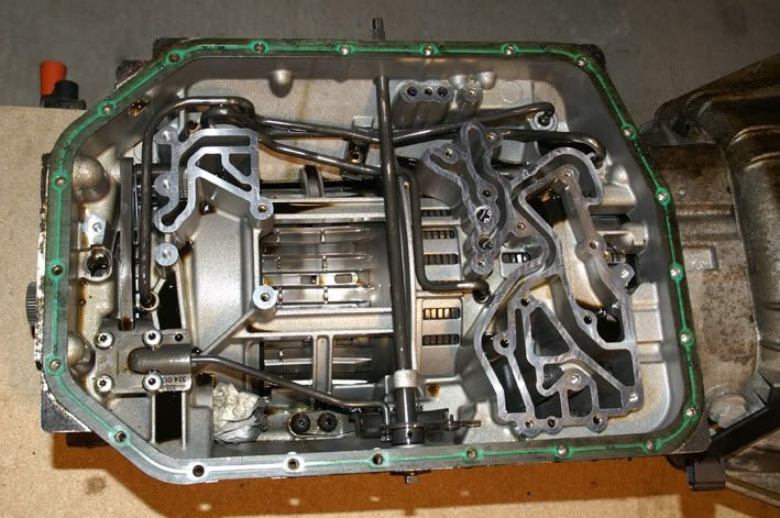
After draining the fluid I removed the sump pan – magnets had the ‘normal’ amount of debris attached. So far so good
![Image]()
Filter is next – date stamped 2002, so it’s obviously never been changed
![Image]()
![Image]()
Next off is the valve block assembly
![Image]()
Everything looking okay, so far
![Image]()
Park lock mechanism and selector detent and shaft are removed next
![Image]()
Followed by the B, E & F clutch feed pipes and the C & D clutch jump tubes
![Image]()
Moving to the back of the transmission, the rear cover & park lock gear are next
![Image]()
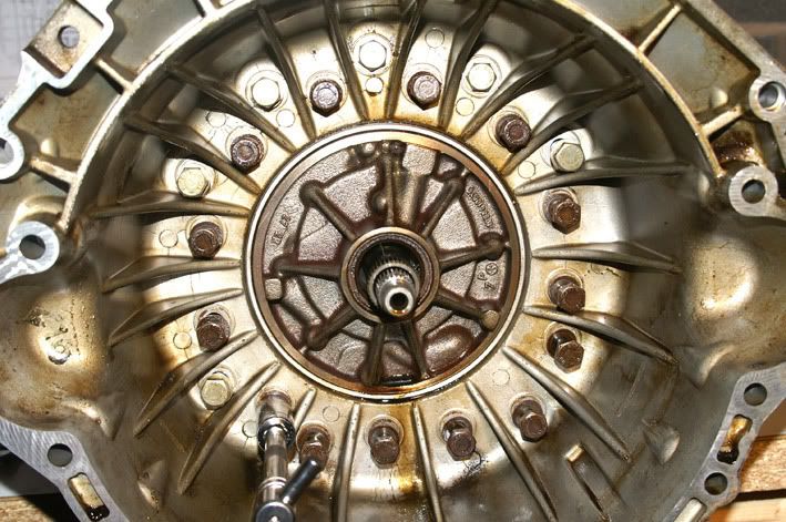
The next job is to slacken off the F clutch drum retaining screws. This drum is the very last part to come out of the transmission but it’s important to slacken the screws off now while the transmission has some weight in it because they’re countersunk and are always stubborn to get out.
![Image]()
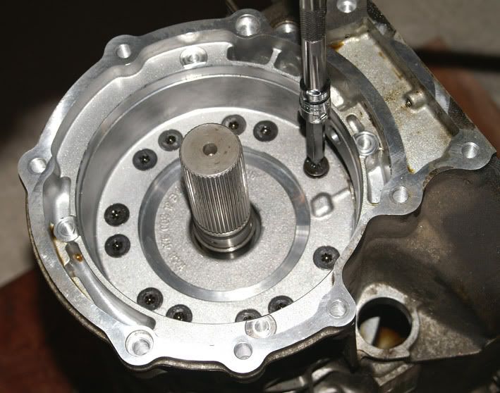
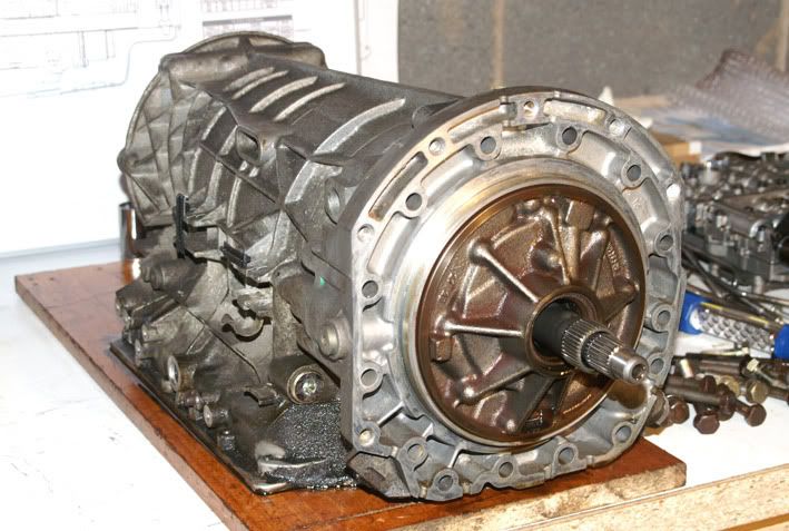
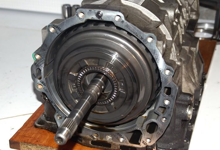
Then around to the front end of the transmission to unbolt the bellhousing
![Image]()
![Image]()
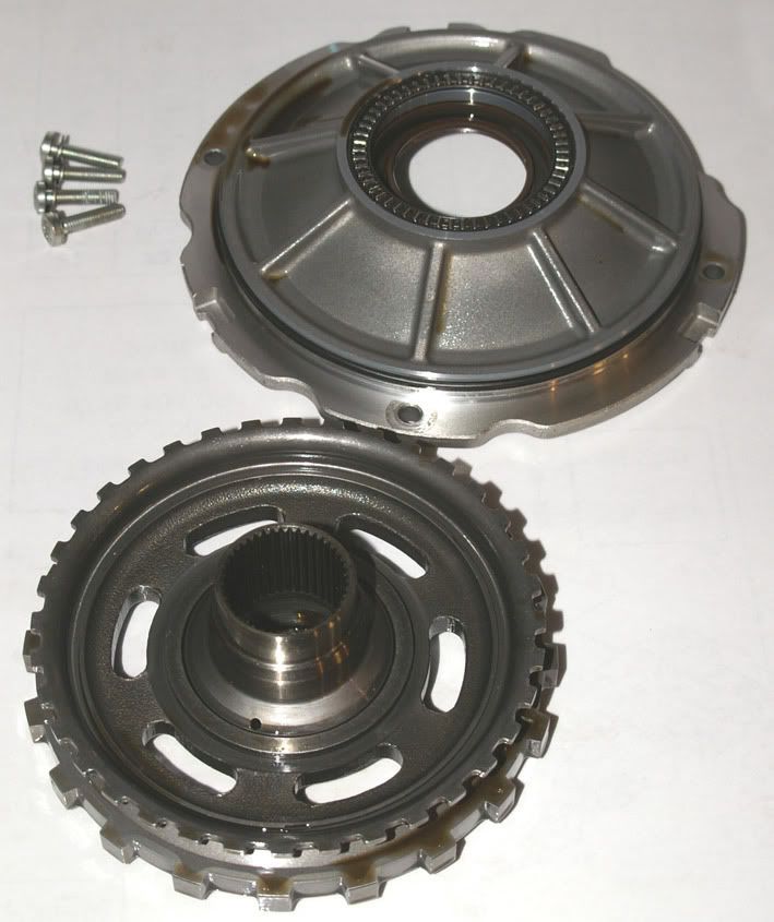
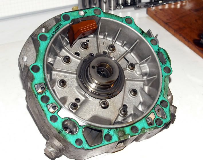
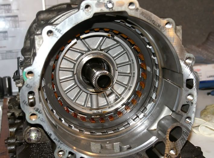
Followed by the intermediate casing (which houses the oil pump)
![Image]()
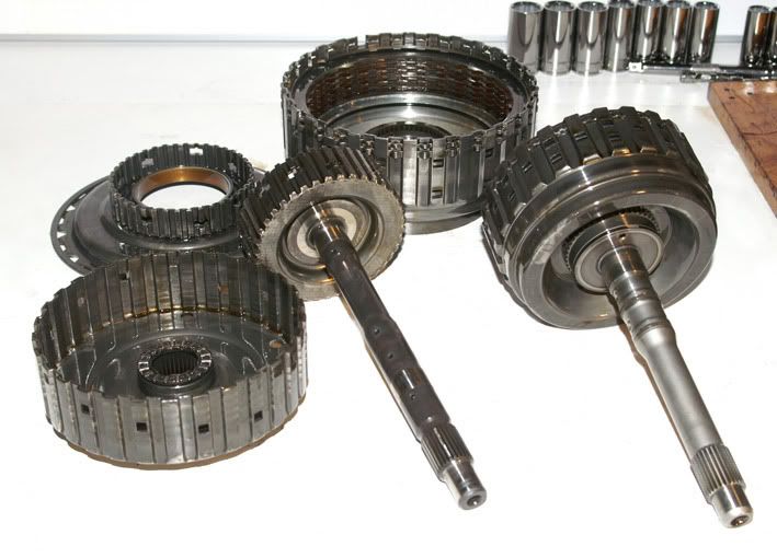
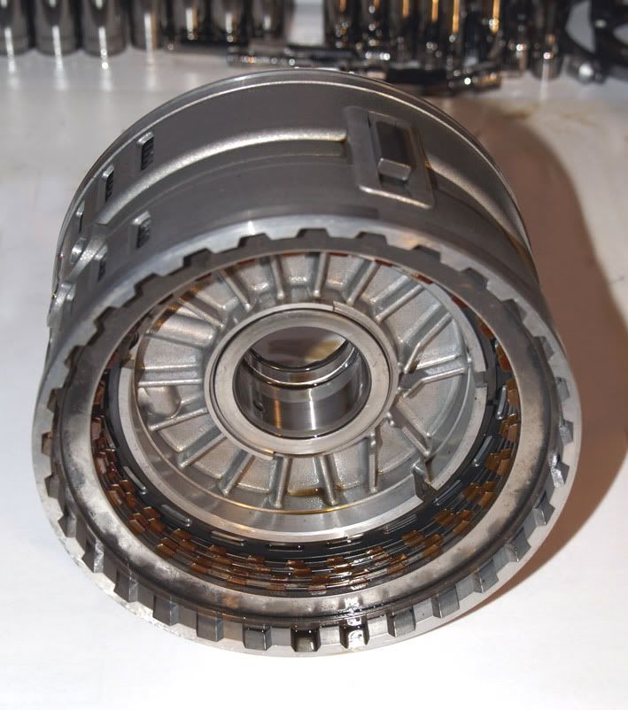
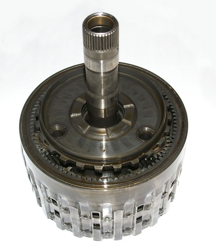
‘Tower 2’ pulls out next – which is basically the A & B clutch assemblies with their respective shafts
![Image]()
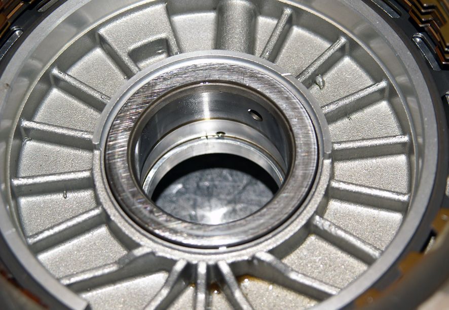
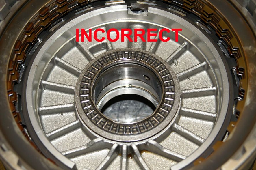
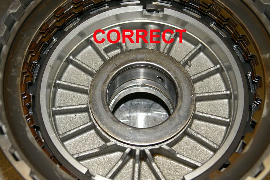
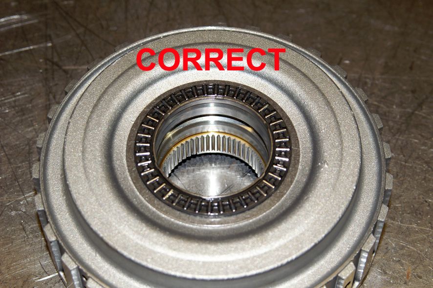
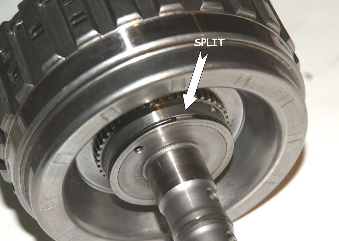
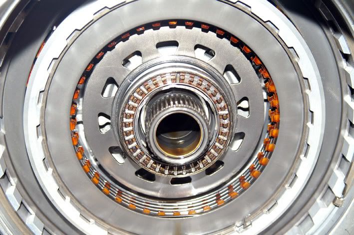
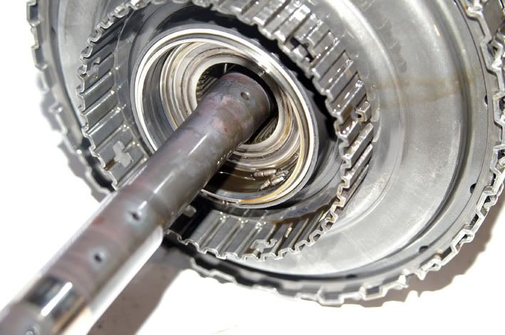
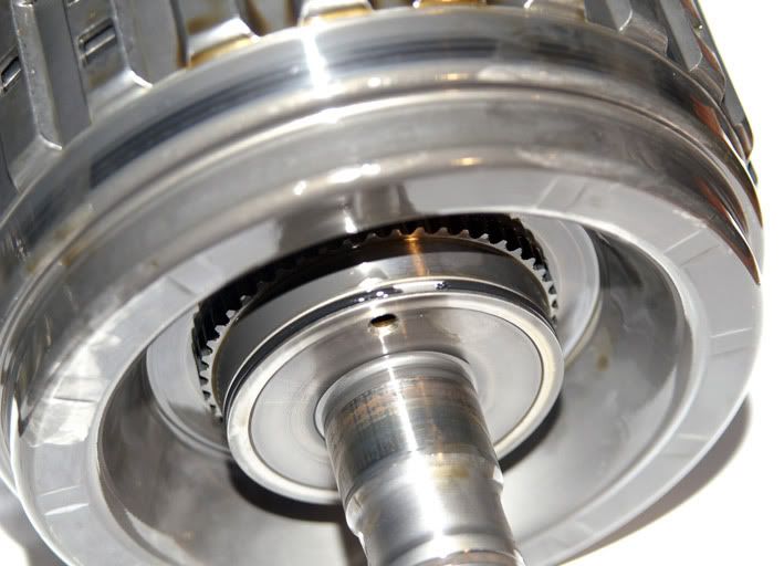
The first clue as to what was wrong with the transmission now emerges! The axial needle bearing which separates the B clutch hub from the C clutch drum has worn to the extent that many of the rollers have come out of the bearing cage.
![Image]()
Loose needle rollers trapped in the B clutch hub – all worn to a taper
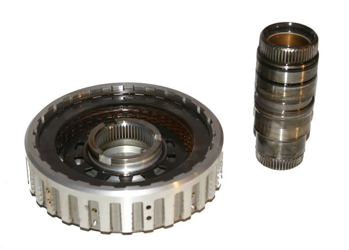
Having seen exactly the same thing on previous Range Rover transmissions that I’ve rebuilt I know where to look for the cause and sure enough, having separated the A & B clutches, I can see that the O-ring which seals between the B clutch drum & the input shaft has failed
![Image]()
The resulting leakage here prevents the A clutch generating sufficient clamp pressure causing it to slip under load and, as it’s used in gears 1-4, the control system detects the slip and protects the transmission by upshifting all the way up into 5th gear – usually with a bang – each time the vehicle sets off from rest
![Image]()
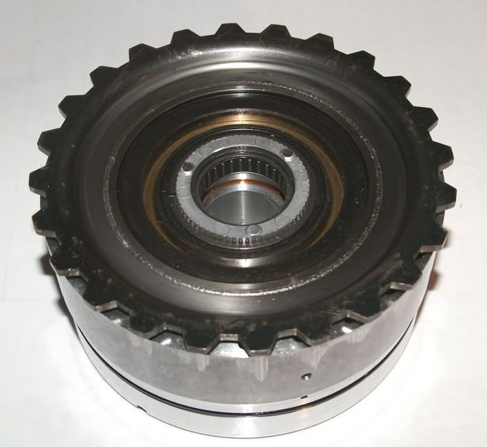
A & B clutch assembly unassembled
![Image]()
The C clutch & front sun gear drive sleeve then pull out
![Image]()
![Image]()
Followed by the D/E clutch assembly…
![Image]()
…the epicyclic geartrains…
![Image]()
…and then finally the F clutch & 1st gear sprag assembly
So, apart from the failed O-ring & the consequent damage to the axial needle bearing, everything else looks in great condition.
A new bearing costs £7 and I’ll replace the A clutch friction plates which is a further £30. The failed O-ring is part of the overhaul kit (£145) so with new fluid & a new oil filter, plus the £50 I paid for the transmission and the delivery charge we’re looking at a grand total of just less than £400 for a fully reconditioned transmission – not bad.
Phil
It cost me another £53 to get it shipped the 230 miles from the seller to my house.
I took a few photos as I stripped it down in case anyone’s interested:
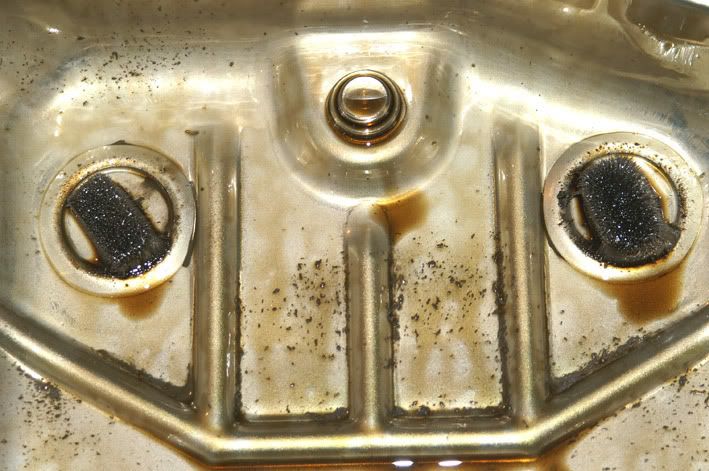
After draining the fluid I removed the sump pan – magnets had the ‘normal’ amount of debris attached. So far so good
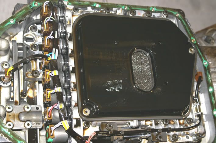
Filter is next – date stamped 2002, so it’s obviously never been changed
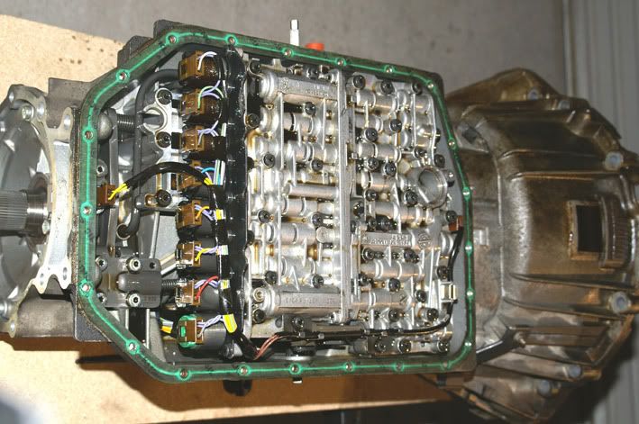
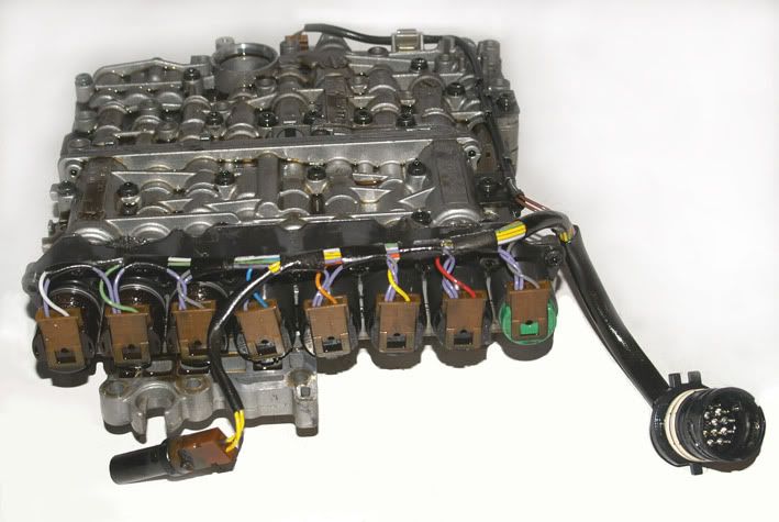
Next off is the valve block assembly
Everything looking okay, so far
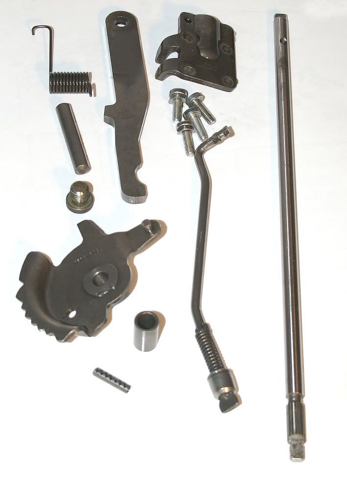
Park lock mechanism and selector detent and shaft are removed next
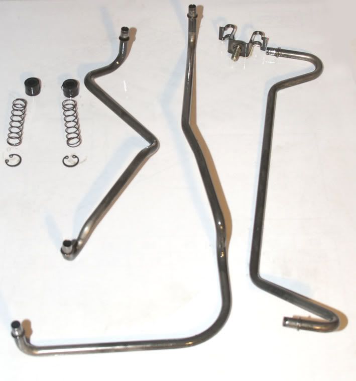
Followed by the B, E & F clutch feed pipes and the C & D clutch jump tubes
Moving to the back of the transmission, the rear cover & park lock gear are next
The next job is to slacken off the F clutch drum retaining screws. This drum is the very last part to come out of the transmission but it’s important to slacken the screws off now while the transmission has some weight in it because they’re countersunk and are always stubborn to get out.
Then around to the front end of the transmission to unbolt the bellhousing
Followed by the intermediate casing (which houses the oil pump)
‘Tower 2’ pulls out next – which is basically the A & B clutch assemblies with their respective shafts
The first clue as to what was wrong with the transmission now emerges! The axial needle bearing which separates the B clutch hub from the C clutch drum has worn to the extent that many of the rollers have come out of the bearing cage.
Loose needle rollers trapped in the B clutch hub – all worn to a taper
Having seen exactly the same thing on previous Range Rover transmissions that I’ve rebuilt I know where to look for the cause and sure enough, having separated the A & B clutches, I can see that the O-ring which seals between the B clutch drum & the input shaft has failed
The resulting leakage here prevents the A clutch generating sufficient clamp pressure causing it to slip under load and, as it’s used in gears 1-4, the control system detects the slip and protects the transmission by upshifting all the way up into 5th gear – usually with a bang – each time the vehicle sets off from rest
A & B clutch assembly unassembled
The C clutch & front sun gear drive sleeve then pull out
Followed by the D/E clutch assembly…
…the epicyclic geartrains…
…and then finally the F clutch & 1st gear sprag assembly
So, apart from the failed O-ring & the consequent damage to the axial needle bearing, everything else looks in great condition.
A new bearing costs £7 and I’ll replace the A clutch friction plates which is a further £30. The failed O-ring is part of the overhaul kit (£145) so with new fluid & a new oil filter, plus the £50 I paid for the transmission and the delivery charge we’re looking at a grand total of just less than £400 for a fully reconditioned transmission – not bad.
Phil