Range Rovers Forum banner
81 - 100 of 119 Posts
Discussion starter · #81 ·
I hope my transmission gets to a quarter of a million miles, like yours has!

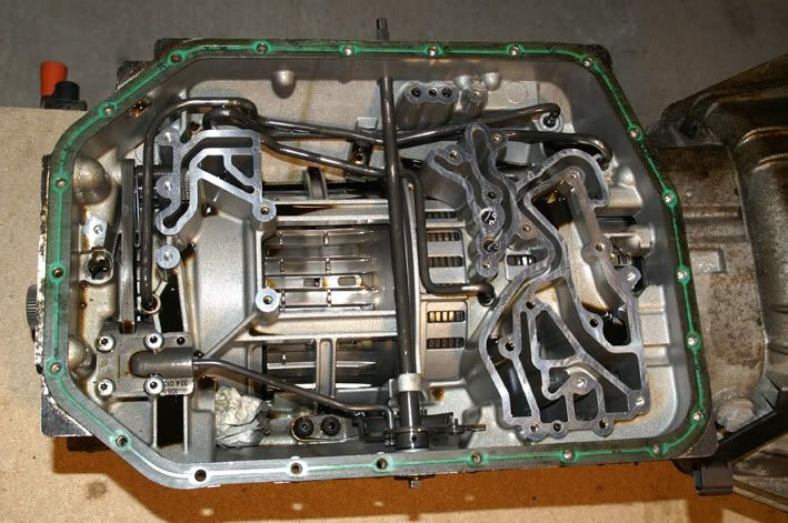
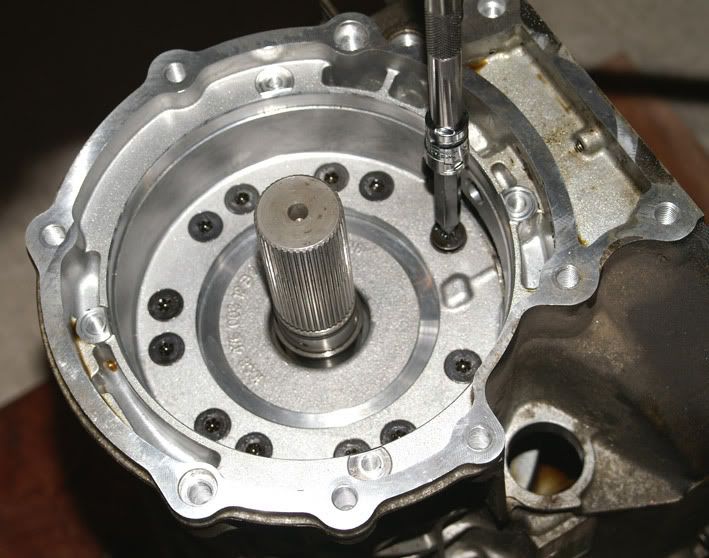
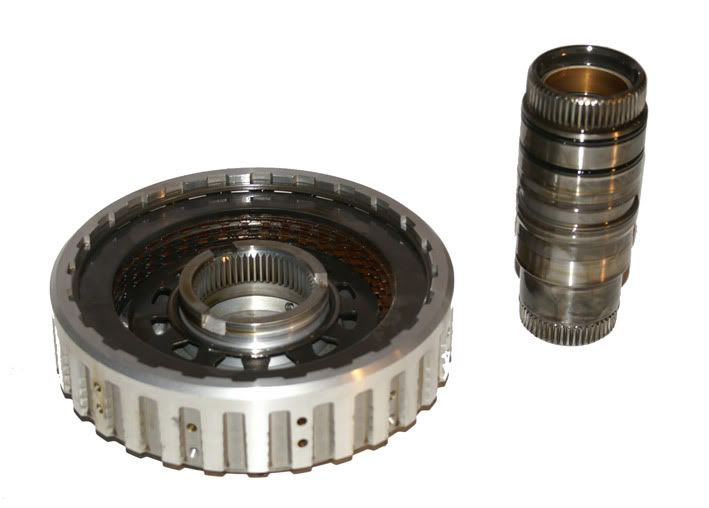
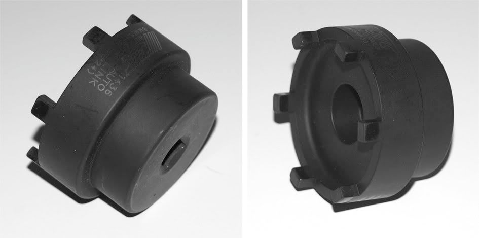
This is the tool I use for the output nut on the Jaguar & BMW transmissions (but not on Range Rovers)

Image


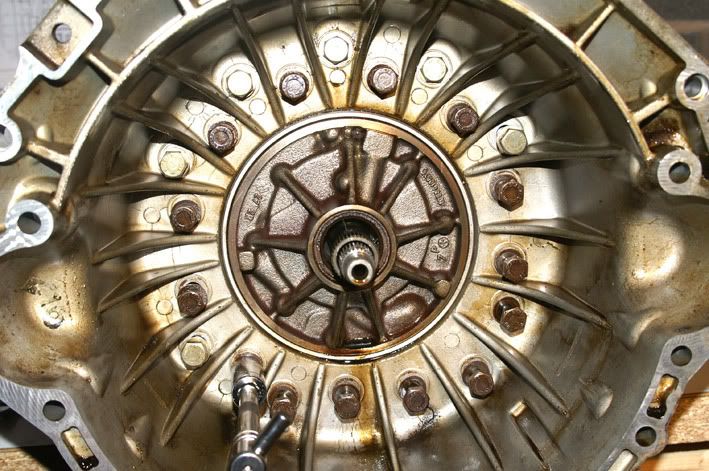
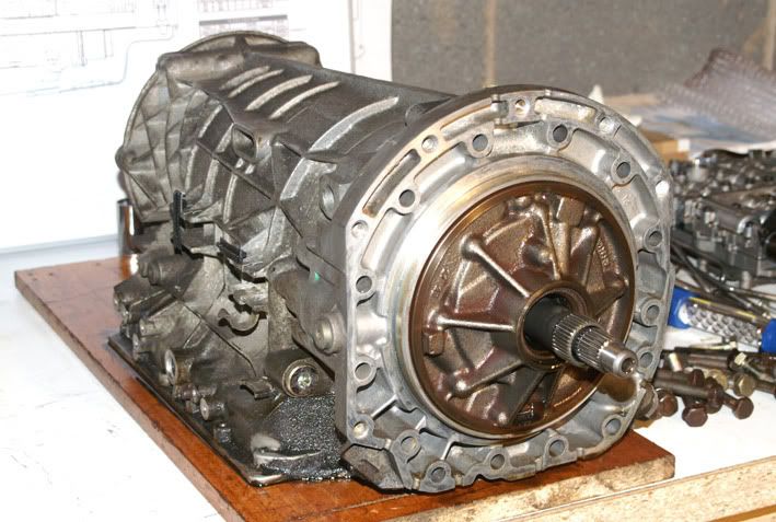
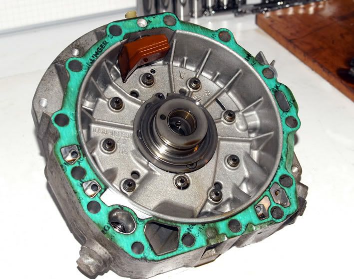
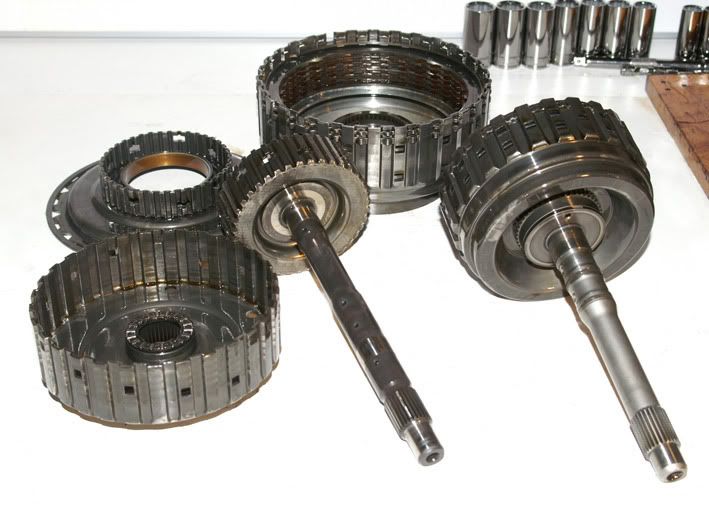
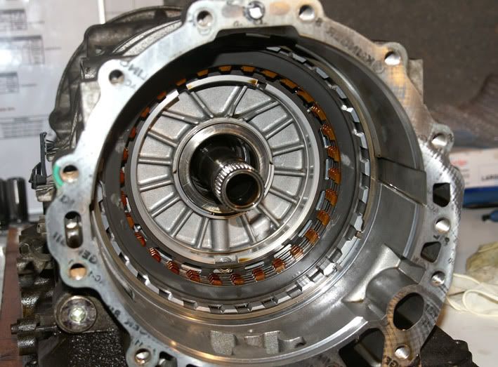
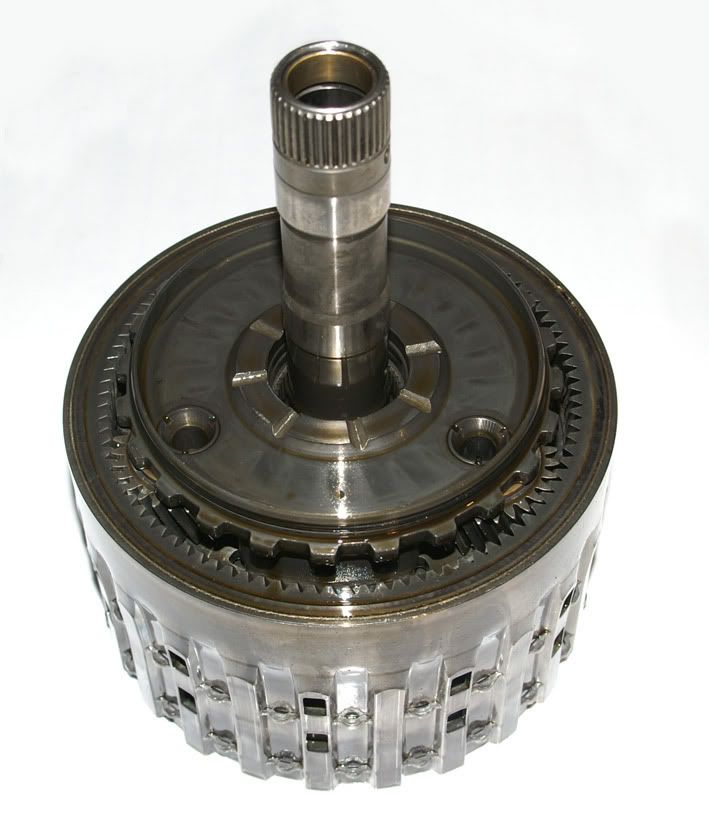
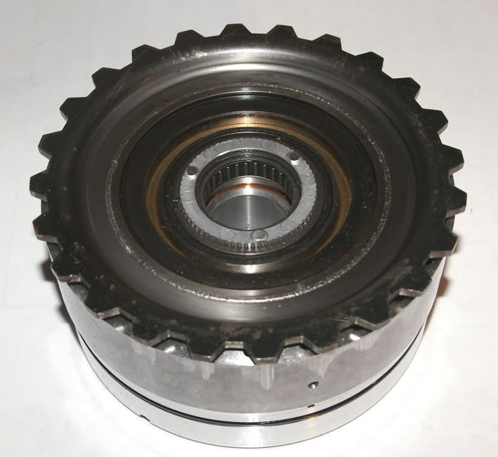
I love seeing the ingenuity that people use to compress the clutch return springs. Here’s a couple of photos from another forum where the guy is also currently rebuilding his 5HP24.

Image


Image


Fantastic! I might start a competition.....

Phil
 
Great pictures!


I have the special tools at ZF Germany asked, A B C D E F and the output nut.


The entire price for everything would have been more than €3500! 8-0=


There you can be like what a fall, and craft a bit
The output nut is over €400 at ZF 8-0=

Christoph


Hi Phil, first of all, fantastic thread and info. I am not a mechanic or an expert but I've been tearing down and rebuilding my 5hp24 in this thread on bimmerforums.com: http://forums.bimmerforums.com/forum/showthread.php?2023324-My-5HP24-Rebuild-Thread&highlight=5hp24. I am having issues with the input shaft so I sent the pump and A/B drum to a local trans shop to check clearances and play. I don't have the machine shop to replace the race in the pump shaft with such a tight clearance. However, I have a question: What is an easy method of measuring clutch pack clearances? Here's how I do it. I install the papers and steels in the drum without the spring steel on the bottom. Then install the retaining ring. Insert a large screwdriver between the retaining ring and top steel and twist. Measure the distance from the top of the retaining ring to the top of the steel (L). Then measure the thickness of the retaining ring (R) and the thickness of the spring steel (S), and use the formula L-R-S=clearance. I wonder if the twist on the screwdriver is applying too much pressure since even with new papers and steels I am still about 1 mm too wide on the clearances, using the retaining rings that existed in the trans to begin with. Any advise would be appreciated. - Bill
 
Discussion starter · #84 ·
Hi Bill and welcome to the forum `8)

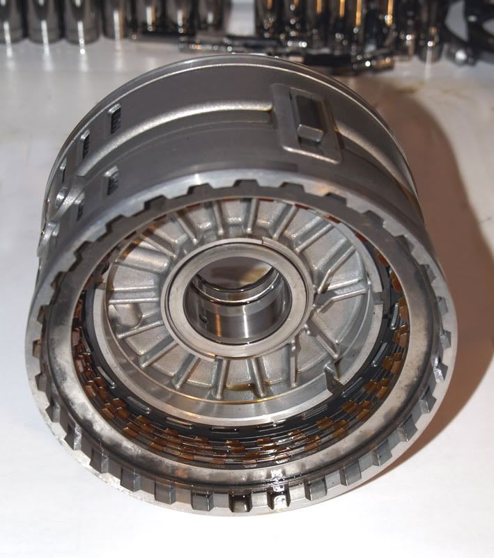
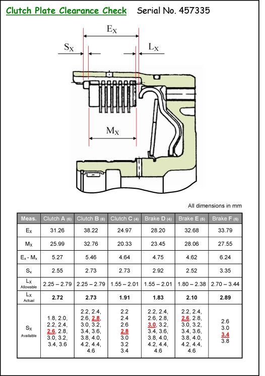
The correct method is to measure each clutch pack thickness (i.e. end plate + frictions + steels + wavy plate) while it’s being compressed with 200N of force. I use a 20kg weight for this purpose. This load compresses the wavy plate but doesn’t flatten it completely so there’s no other way of correctly determining the pack thickness I’m afraid. You then measure from the top of the snap ring groove to the piston face. Subtract the (200N) pack thickness, subtract ZF’s specified clearance, and you’re left with the snap ring thickness required.

Image


Phil
 
Thanks Phil, I got the trans running and so far so good, but only tested it for about 20 miles so far. One thing that concerns me is a clicking/tapping sound from the bellhousing area. After it gets warm the area smells like something is really hot and burning, like maybe trans fluid, but INPA shows internal trans fluid temp as 88C. I think if the torque converter or oil pump were the culprits they would also overheat the oil. The sound follows engine rpm and since the first start has gotten more faint. I know this is a stab in the dark, but with your experience level just wondering if you've heard of this before.
 
I finished the rebuild, and have put about 500 miles on it. Full success! Runs better than I can remember it in the past.
Well, here it is almost a year and about 8,000 miles later, and I have a new problem. I was visiting about 350 miles from home, and all of a sudden NO REVERSE! We drove home just being careful to not put the car in a position that would need reverse to be used. Driving was normal, no problems at all driving forward.When I got home, before pulling into the garage, tried reverse, and it worked! Tried it two more times, working normal. However on the third try, it started reversing normally, then popped out of gear just like I had put it in neutral. Shifted back and forth a couple more times, no reverse. Sometimes now when selecting reverse, it "Jumps" into reverse, but when pressing the throttle, no motion. Other times, nothing happens, but I do hear some light noise in the transmission. I tested the shift position switch with INPA, it works correctly every time. That was my "hope for an easy fix". I then tested the solenoid valve signals with INPA, solenoid valve 1 signal actuates every time it is put in reverse.

I am not sure what to try next. I think I will jack the car up and pull the connector to check resistance on the solenoid valves. However, it seems that there is no solenoid that works only in reverse, so if a solenoid was bad I would expect more than just reverse failure.

When I rebuild the unit, I used a ZF kit, all new frictions and seals, and a ZF valve body repair kit. So everything normally replaced in the unit should be only a year old. I also used Pentosin ATF1.

Any suggestions from anyone?
 
I know it sounds daft but have you rechecked the auto box oil level before tearing down parts of the box. Sometimes we forget the basics first. If you have sorry for this reply :)
 
Discussion starter · #88 ·
David,

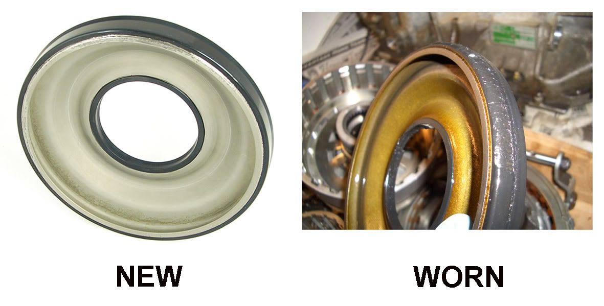
Yours is a BMW 540i/740i transmission isn’t it? Out of interest, did you replace the F-brake piston when you rebuilt your transmission? I just wondered if you were getting engine braking when you select 1[SUP]st[/SUP] gear in Manual mode?

Image


Phil
 
Yes, it is a 740iL. I replaced the F piston with a new one. The shift lever only allows selecting 2,3,4 and D, not first gear. I tried just starting out and letting off the throttle before it shifted to second, and I THINK it is engine braking, but hard to tell since the 1-2 shift happens pretty quickly.

I will be getting the car up on stands tomorrow, and will pull the pan to see if anything is in it, and to check the solenoid resistances. If all looks good, I will drop the VB and do pressure tests on the C and F clutches.
 
Phil, sure glad to see you answer my post. You seem to be the world expert on these boxes as far as DIY is concerned.
I do have one question: I checked the solenoid signals with INPA, and solenoid 1 is activated in Reverse. The only thing I could find regarding which solenoids are activated is an ATSG tech bulletin, and it shows solenoid 2 activated for reverse. I have the ZF service manual, but can find no reference as to which solenoids are activated for each mode. Is there anything written by ZF which shows this?
 
Discussion starter · #91 ·
Unlikely to be solenoids I would have thought i.e. none of them are used uniquely for reverse so you’d expect to have issues with other shifts too. This is ZF’s published logic for the eight solenoids :

Image


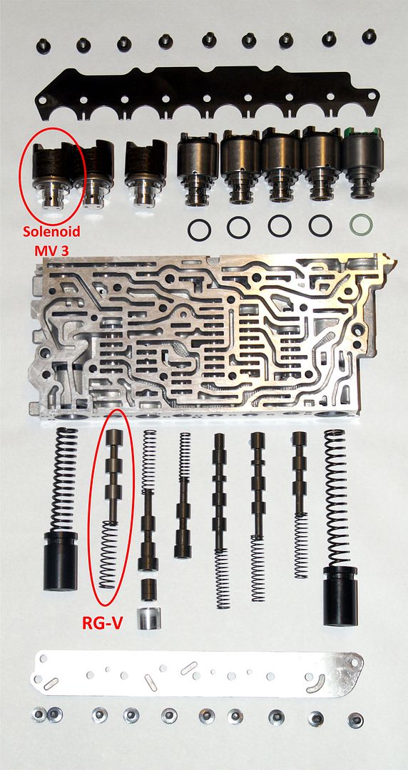
Out of interest, shift solenoid 3’s only purpose in life is to act as a safety device in case the driver accidentally engages reverse using the shift lever while travelling forward at speed. It applies pressure to the reverse gear protection valve (RG-V) to override the manual valve’s hydraulic signal to engage the C/F clutches. I guess there’s an extremely slim possibility that your reverse gear valve might be sticking?

Image


I agree that a pressure test of the C-clutch & F-brake hydraulic feed circuits is a very sensible next step.

Phil
 
Thanks for that chart! It agrees with the ATSG chart, in that SV2 should be energized when Reverse is selected. INPA shows that when I select reverse, SV1 is energized! Now I am thinking that something electrical has gone awry.

I have to check my software to see if something besides INPA shows the solenoid data for a second opinion. I don't think DIS/GT1 does.

Strangely, even though SV1 is shown energized, I sometimes get a hard thump when selecting reverse, then no drive. Going to hook INPA up again and watch it closely to see if SV2 is energized briefly, although it may not show it due to software lag. I may find a place to hook a meter to see if SV2 is "bumped" when shifting to reverse. If SV1 is on, and SV2 is energized, that could account for the thump.
 
Discussion starter · #93 ·
That’s very strange. It’s definitely Shift Solenoid 1 (the on-off solenoid which activates pressure on all three shift valves) rather than Pressure Regulator Solenoid 1 (which controls the ‘mains’ pressure for the complete hydraulic circuit) which is being identified by the diagnostic kit? Clearly Pressure Regulator Solenoid 1 is activated the whole time, unless the transmission engages failsafe mode due to an electrical failure.

Phil
 
I just finished putting LEDs on the Solenoid 1,2 and 3 lines out of the controller. All seems to be proper except that only Solenoid 1 is on when reverse selected. All solenoid activation is proper, neutral through 5th gear.

When reverse is selected, solenoid 1 stays on, no indication of any signal to solenoid 2, but I sometimes do get the "Bump", like it is trying to shift, but no drive. Could that be the mechanical shift, but without solenoid 2 on it drops out?

I guess I will order a used EGS module to test.
 
Yes, they are actually designated MV1, MV2, and MV3. The diagnostic software does not monitor the regulator solenoids, only the three shift solenoids.
 
I am really frustrated now! I just put in another EGS module, with the same results. I have read everything I can find on the internet, but cannot come up with a reason the EGS would not turn MV1 off and MV2 on when reverse is selected. The input lines are correct for gearshift selections on all gears.

I ran full car diagnostics with DIS, no errors found. INPA finds no errors in the EGS module.

My back is against the wall now. Does anyone have any ideas on what I could check next? The car runs just fine in all forward gears, and the solenoid lines change as expected in each gear forward, but not for reverse.
 
Discussion starter · #97 ·
What seems most strange to me is the fact that reverse doesn’t actually appear to engage. When reverse is selected on the gear lever the manual valve in the valve block directs mains pressure fluid directly to the C & F clutches – with only the reverse gear protection valve in the way. Provided that the RG-V valve isn’t activated by solenoid MV3, or sticking open, the C & F clutches should be engaged irrespective of the status of the two remaining shift solenoids (MV1 & MV2). The hydraulic circuit is designed this way so that, even in the event of a complete electrical failure to the transmission, 4[SUP]th[/SUP] gear and reverse are still available.

I was wondering if a possible consequence of the wrong solenoid being switched on might be that a third clutch is being engaged (in addition to C & F) which would result in the whole geartrain being locked solid (obviously the torque converter still slips). If the car is on a slight upward slope and reverse is engaged will the car roll backwards with the brakes off?

Phil
 
I put a switch on the MV1 and MV2 lines to switch them properly when I shifted to reverse. That did not work, but put the transmission into failsafe mode. When I tried reverse with failsafe active, it would try to reverse, but would slip with much more than idle throttle.

I have pulled the tranny and have it on the bench now. I did the air test, and the C clutch air is blowing through pretty massively.

I have partially disassembled the unit, and the only thing I have found is that the end bushing in the stator shaft has shifted all the way forward, flush with the end of the stator shaft, where it should be seated against the shoulder, about 10MM back from the end. Looking at the assembly though, don't think that would bypass all the air. All seals look good though.

I had replaced the bushings when I rebuilt the tranny, but as I stated at the time was not at all happy with the clearance, nearly 0.004". I think I will order some bronze stock and make two new ones. I did make one new bushing when I rebuilt the tranny, but did not have stock large enough for these.

I did disassemble the C clutch, looks new, and I remeasured the clearance, only slightly measurable difference from the measurements I made first time, so the clutch is still in great condition.

I am going to put the tower back together with the re positioned bushing to see if that makes any difference. I am still thinking I will make new bushings though, as the one that had moved did not have much of an interference fit I pushed it the rest of the way out by hand! Don't know if I mistakenly installed it flush with the end, or it moved under pressure, but I want to know it is installed with proper interference this time, also want about 0.001" clearance instead of 0.004"

Phil, could you look at your fluid flow information and tell me what you think would happen in reverse if MV1 is on instead of MV2 (what my two controllers are doing)? It is strange that two controllers would do this, with no error codes.
 
I have partially disassembled the unit, and the only thing I have found is that the end bushing in the stator shaft has shifted all the way forward, flush with the end of the stator shaft, where it should be seated against the shoulder, about 10MM back from the end. Looking at the assembly though, don't think that would bypass all the air. All seals look good though.
I meant to say SUN shaft, not Stator.
There seems to be no way to edit posts on this site.
 
Discussion starter · #100 ·
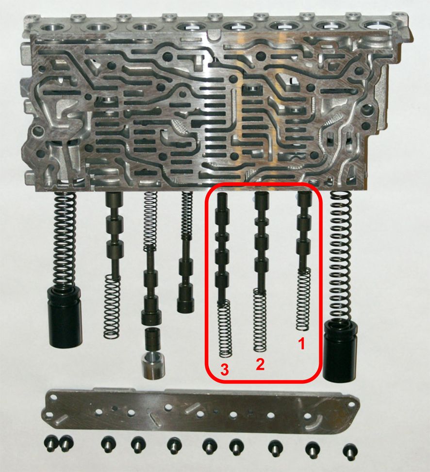
The two shift solenoids, MV1 & MV2, between them control the positions of the three shift valves situated in the lower rear valve block.

Image


Each of the three shift valves has only two positions – which I’ll call ‘up’ and ‘down’ (just because that’s how they appear on the circuit diagram). Each valve defaults to the ‘up’ position, due to spring force, when no hydraulic pressure is applied.

The shift solenoids apply 5 bar pressure to the ends of the shift valves to shuttle them up & down.

MV1 acts on all three shift valves to move them to their ‘down’ position.

MV2 acts only on shift valves 1 & 3, holding shift valve 1 in its ‘up’ position and shift valve 3 in its ‘down’ position.

The two shift solenoids are applied in various combinations for each of the gears which, when operating correctly, gives the following result :

Image


and these shift valve positions are achieved by the following sequences of MV1 & MV2 solenoid activation :

Image


As you suggest, I’ll see if I can work out from the circuit what would happen if MV1 is engaged in Reverse rather than MV2.

Phil
 
81 - 100 of 119 Posts