Range Rovers Forum banner

'93 4.2L County LWB engine cuts out under smallest load

6.6K views 38 replies 10 participants last post by  ddindyrr  
#1 ·
When I saw "cuts out", I mean stalls, fires, stalls, fires, etc, to the point that I can't accelerate and it feels like my driveline is going to slam itself into pieces.

Started doing this going down the highway, a "cut out" exactly like it used to do when the ignition amplifier on the dizzy was crapping out. Pulled over like I used to do, but it was idling fine. Slowly accelerated back up to highway speed and drove it 50 mi no problem.

THEN, when I shut it down for 20 min and turned around to come home, I got no more than a mile before it started the stall/fire routine. Drove it home 50 mi on backroads @ 20-30 mph with my hazards on.

It will start and idle perfectly. Will rev freely and hold high revs (3k rpm) while in Park, no problem. But when I put it in Drive and press on the gas to accelerate, it cuts out. I can slowly accelerate up to 20-30 by GENTLY pressing the gas off-idle, and it seems completely dependent on engine "load"; press too hard to apply more load to the engine, and it cuts out. Runs great going downhill when I barely need to touch the gas, but as soon as it turns uphill you can't touch the gas or it cuts out.

Ideas? Pertronix dizzy ~10k miles ago, fuel pump and filter replaced ~20k miles ago. New plugs 500 mi ago. Again: Starts up, idles, and revs fine.
 
#3 ·
Given the role call of parts (not absolutely a guarantee of no faults) I'd initially suspect TPS as posted above.

It has, more or less, two function. One of overall position of the air flap (giving accurate metering information for constant state fuelling) but the other, and really important contribution is the rate at which you open the throttle system. With that function impaired it will usually give the symptoms described.

Effectively that secondary function takes the place of an "accelerator pump" on a carburetor and provides richer mixture temporarily to stoke the fires and get it cracking along as you increase the demand on torque. The quicker you demand it the more important that function is.
Very light running makes little demand on fuelling, but the quick demand for torque will absolutely need it.

The system checks the output voltage of TPS on start up, if that's ok (but the further rotation, that isn't checked) is at fault, then it'll give this type of driving usually.

You can unplug the TPS and try driving it as it may improve (this is just to test function, not a cure) as the ECU will recognize the TPS signal is abnormal to start with and run something of a competent map to help, it may drive better (so helpful for diagnosis) but won't be fully covered to produce perfect running. As already said it may help diagnosis if you took it for a run with TPS unplugged and report observations.
 
#4 ·
Given the role call of parts (not absolutely a guarantee of no faults) I'd initially suspect TPS as posted above.
Where might I find the TPS on this rig, and is there a reason why I might not want to just swap it out for good measure? To eliminate it as a possibility? I am starting to feel better after 11 yrs of ownership of having replaced ALL bolt-on replaceable components (except PS box/pump), so why not the TPS also?

As a side note, the rig just turned 200k miles about 100 mi ago, on the original engine and drivetrain. I don't believe the heads have ever been pulled, and last summer I got over 17 mpg on a 400-mi highway rnd trip @ 70-75 mph. Oh, it's feeling and looking it's age all right, but it's still a dream to drive down the road.
 
#5 ·
It's located on intake system, following from air filter, then to MAF, then through the flexible hose to plenum chamber, it's located on the front facing part of plenum.

Only small about 1 1/2 inches across, a small black plastic circle shaped with two "ears" and plain screws holding it in place. Safe to remove (it just has similar to a screwdriver blade backside that allows the throttle to turn via engagement) and has a round plug connector to electrical loom.

Original now unavailable, alternative Tornado Systems | ACT ROVER V8 14CUX replacement throttle pot TPS /throttle position sensor is a newer design being sold to straight fit. Pricey by comparison but not much alternative if you need one.

At the mileage you have it's odds above even that it's worn (they have a carbon track inside with a "wiper" that gives variable resistance in reporting throttle position) but that cost implication makes me circumspect in saying it's a definite fix, hence the suggestion to experiment. At least if you understand the risk you can form your own view.

Alternatively, this one seems to be the supply part for that other link Colvern CP17 Throttle Position Sensor TPS - SPOOX MOTORSPORT | eBay but I've not had to use either supply yet as original still ok on mine.

The item itself has definitely been used by other forum members and all seems good from that aspect.
 
#16 ·
Original now unavailable, alternative Tornado Systems | ACT ROVER V8 14CUX replacement throttle pot TPS /throttle position sensor is a newer design being sold to straight fit. Pricey by comparison but not much alternative if you need one.

Alternatively, this one seems to be the supply part for that other link Colvern CP17 Throttle Position Sensor TPS - SPOOX MOTORSPORT | eBay but I've not had to use either supply yet as original still ok on mine.

The item itself has definitely been used by other forum members and all seems good from that aspect.
I pulled mine off and will do a bench test tonight, but comparing it to both of the options listed above, I can't see how either is a bolt-on solution. The original has a blade-post that slips into a drive slot in the plenum, and neither of the items listed show a protruding blade-post.
 
#8 ·
Something else to look at is the alternator. I had a very similar issue and spent a bunch of time and money replacing engine management sensors with no change. When running on the freeway under light load there's a considerable amperage draw on the system to run various systems (ignition, fuel injection, engine management, etc.) and if the alternator is not able to meet the demand systems start cutting out. Mine was cutting the fuel injectors. I was able to duplicate the issue by using a VAT40 machine to put a substantial load on the electrical system. 40 amps of additional load at 2500 rpm was what it took to duplicate the issue statically in my driveway. Free revving the engine will not duplicate the necessary load. It should be noted that I took the alternator out and tested in at my local parts store and it passed.

Replacing the alternator fixed my condition.
 
#9 ·
Replacing the alternator fixed my condition.
Funny you should mention the alternator, and I DID run across your old post(s) describing your alternator revelation.

As it happens, I replaced my alt maybe 4k miles ago because when I put the new radiator back in and added new belts, there was a squeal on startup that I isolated to the alternator, and no amount of belt adjustment (with the ridiculous OEM adjuster) would make it stop, so I was advised that it was probably an alt bearing that was squealing on startup. So new alternator and...wait for it...squeal was still there. GRRRRR! At this point I was fed up with wrestling that ridiculous OEM adjuster, so I modified it to behave like any old '70's GM alternator adjustor, AND THE SQUEAL WENT AWAY FOREVER. Original alt was good after all.

BUT, I kept the new alternator in there, and NOW I see the dash light glowing slightly at idle or when the rear window defroster is on at low revs, WHERE I NEVER SAW IT GLOW BEFORE.

So your point is taken about the alternator, maybe my new replacement somehow doesn't put out the same amperage as the original?
 
#10 ·
I have not had luck with new/rebuilt units from big box parts stores. I usually keep a good working original unit on hand just in case. My truck has nearly 200k miles and still has the original alternator and performs well. It might be worth swapping in your old unit to see it it has any affect. The warning light should not be glowing at idle under any condition.
 
#11 ·
You can diagnose the TPS with a multi meter
Disconnect the connector : there are three wires to it
Different years have different colors and I don't remember them, but that doesn't matter.
Thre wires mean three possible couple of wires (you follow?)
One couple has a constant resistance no matter the throttle plate position
The other two couples have a variable resistance, depending on the position of the throttle: one decreases, the other one increases.
They should change linearly across the whole position range.
In my '92 one the resistance of one of the couples would decrease linearly for about 50% of the range, then do straight to short circuit.
That's how I positively knew that the sensor wasn't good.

I bought a Toyota TPS on Amazon for like 5 euros, made a mock up of the Colvern adapter plate with a drill press in my garage, and installed it.
The biggest expense was finding the right connector to it... but it's a standard Denso part, not too hard to obtain.
Point is, any TPS can work if you wire it properly.

Image
 
#20 ·
I bought a Toyota TPS on Amazon for like 5 euros, made a mock up of the Colvern adapter plate with a drill press in my garage, and installed it.
The biggest expense was finding the right connector to it... but it's a standard Denso part, not too hard to obtain.
Point is, any TPS can work if you wire it properly.

Image
Suuuuuure do wish I could see the business-side of your adapted Toyota pot, they're easy to find on ebay that looks just like that, but the other side is typically a female X-shaped receptacle with open sweeps between the points and I don't know HOW a cylindrical shaft is adapted to that, plus: I don't see any Colvern portion of your rig, looks like just the Toyota part is bolted up.
 
#12 ·
I was trying to find your TPS mod Tex and couldn't remember where it was. Certainly of interest here.

Something also that may influence diagnosis, the displayed code for TPS fault I think only displays for being out of range at initial switch on when it's checked (can't immediately find anything contrary to that) but they seem to fail further up and once you start opening the throttle. The "range" reported then treated as bonafide information (which is wrong) and not subject to any logic testing during running.
Potentially, if that's true, it could be faultless from onboard diagnosis records but still be failing during use and when most needed.
If you pull the TPS plug then start it, the code should be initiated then I thought, but with the ECU running "intermediary" data it could respond better in this state as it acknowledges it's need to run with a failed TPS under inbuilt contingency.
As already mentioned, not a fix, but may help with cheap diagnosis as way of determining if there's improvement.
 
#13 ·
Not that familiar with the RR Classics but if you have a distributor you also have a coil? Same symptoms a long time ago with an MG-A. Turned out the coil was slightly loose and couldn't stand up to the increased load on the plugs. A good look at the spark plug leads and the distributor for frayed wires also comes to mind. Hope you can solve your problem.
 
#15 ·
Circled back to this thread to see what new info might've been posted, thanks again for the input. Between my disgust in needing to fix this thing AGAIN, and the insane weather here, I haven't opened the hood since I parked it with this problem, although I DID start it the other day, started and ran like a swiss watch. At idle with light throttle.

So my next plan is to check the TPS via Tex's (and others) method, then source a replacement. I know that's what it is, checked every wire and connection otherwise.
 
#17 ·
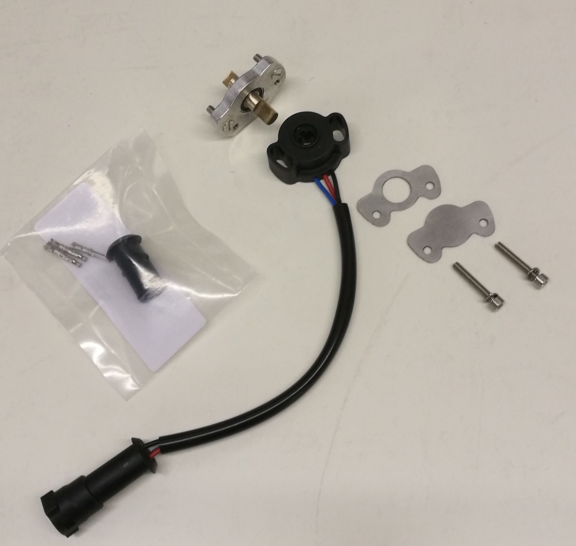
They come with ad adapter plate and a little shaft with two blades - one per side. If they don’t, you need to make your own.
I thought that the price for it was outrageous so I ordered a 8mm ID bearing and after 10 minute with a drill press and 5 minutes with a file I made my own plate and shaft. And since I was doing it from scratch, I used a cheap generic Denso TPS, made for Mazda or Toyota I think.

This is what a complete kit should include

The most expensive part of putting this together is the connector, but it’s the same connector of the front corner lights so it’s easy to get one at a breakers yard.
 
#26 · (Edited)
It’s a very thin bearing, but it’s a bearing like any other. Careful not to go overboard with the three punches to hold it in place or it’ll become notchy.

Sorry, one resistance increases and one decreases! I should have re-read that more carefully. Anyway, it’s just a normal potentiometer.

Another way to understand the pin out is to start from the connector: you have three wires. One is +5V, one is ground, one is signal wire and if you play with a multi meter, will look connected to nothing. You want to connect +5V and Ground to the two ends of the resistance strip, which means the two wires whose resistance doesn’t change. The signal wire goes on the wiper contact. +5 and ground have to be connected so that resistance between +5 and wiper is greatest at throttle closed and smallest at throttle open. That way you’ll have +0V at throttle closed and +5 at open.

Edit: or maybe just copy my original thread: you can see how the original wires are spliced into the wires from the pot. You can barely read it, but on the pot itself I wrote with a yellow marker - (for ground), + (which stands for +5V), and S (signal).
 
#27 ·
Another way to understand the pin out is to start from the connector: you have three wires. One is +5V, one is ground, one is signal wire and if you play with a multi meter, will look connected to nothing. You want to connect +5V and Ground to the two ends of the resistance strip, which means the two wires whose resistance doesn’t change. The signal wire goes on the wiper contact. +5 and ground have to be connected so that resistance between +5 and wiper is greatest at throttle closed and smallest at throttle open. That way you’ll have +0V at throttle closed and +5 at open.

Edit: or maybe just copy my original thread: you can see how the original wires are spliced into the wires from the pot. You can barely read it, but on the pot itself I wrote with a yellow marker - (for ground), + (which stands for +5V), and S (signal).
Tex and all:

Can anyone post the wiring identifiers (colors, function, +, -, output signal S) for the '93 or '94 4.2L engine TPS harness?

I finally created an adapter plate, shaft, and installed a Toyota TPS unit identical to the one in Tex's great photos. Problem? I cannot be sure I wired correctly @ the factory plug, and as it starts and runs now (have NOT driven it on the road), the tach doesn't work and the CEL is on.

I drove this thing SLOWLY around the yard a few times in the past 6 months since I pulled the bad factory TPS off and have been "making" a version same as Tex's, and in that entire time the tach hasn't worked and the CEL has been on, leading me to believe that NOW that I've installed my unit, I got the wiring wrong.

I verified the 3 wires on my replacement Toy unit as functioning the same as Tex's blurry labeling in his photo (-, + which looks like an "A", and S), but in predictable RR fashion, the 3 wires in my factory plug ARE DIFFERENT COLORS AT DIFFERENT POSITIONS on my plug ('93 4.2L, I think Tex's was a '92, making it a 3.9?).

Using a multimeter, I found what apparently was the 5V + pin on my plug (by measuring with the key on), a YELLOW wire, and wired that to the + (center) wire of the Toyota TPS.

But the other 2, the - , S wires, are a crapshoot since my original TPS was so shot I couldn't get reliable bench-test behavior out of it to check, so I wired them based on Tex's photo. My colors are different than his, but I wired to the same POSITIONs.

So I think at WORST, I have the - and S wires reversed. But I am afraid to swap these connections for fear of some back-feed weirdness affecting the ECU.

If ANYONE has a wiring schematic that identifies the 3 wires on a '93 4.2L TPS harness, PLEASE post them.

Thanks!
 
#28 · (Edited)
Hi, yes the car I did this mod to is a '91 3.9.
Here is a screenshot I had saved on my phone, I wanted to put a link to the original site but I can't find it any more. If your colors are brown green and blue, you should have all the info you need. My '91 is "early TPS".
Don't look at the colors at the wires in my pictures because the Rover connector I used is a repurposed front blinker one, so wire colors are all different.


Image


I just re-read your post. Your +5 wire is yellow so your case is not in the above list.
I think you can just check which of the other two non-yellow wires has continuity to ground. That's your - wire and the last one is your S wire.
 
#29 ·
View attachment 300639

I just re-read your post. Your +5 wire is yellow so your case is not in the above list.
I think you can just check which of the other two non-yellow wires has continuity to ground. That's your - wire and the last one is your S wire.
Tex: Yes, my +5 wire is yellow, but my other wires are red and green, conforming to the "early TPS" in your chart above. I'll go with that and see if that's how I have it wired. If I have it correct, the non-working tach and CEL must be coincidental and non-related, If I have it wrong, you CAME THRU FOR ME! Either way, you came thru so muchos gracias!
 
#30 ·
Remember to Check if the green wire is actually connected to the ground.
My truck would run with a faulty TPS AMMand kind of ran also with no tps at all, so I doubt that your issues are tps related. But we’ll see.
another information is that my trucks are Euro market, so they have no o2 sensors and are manual. It’s possibile that your US truck has a more complex ECU that will throw CELs more easily than my rudimental one.
 
#31 ·
*//////////////////////////////////////////////]i'[
Remember to Check if the green wire is actually connected to the ground.
I recall that when I first attempted to research the (3) harness wires @ the fixed plug on the harness, I could not get a reliable ground reading from either of the (2) non-yellow wires, which is why I just followed your pic for the - and S wires. I'll look at that again, but is the ground a HARD ground with key on or off? The ground isn't dependent on any switching thru the ECU?

If I can't verify a ground thru the harness that may be a compounding problem, and I'll have to run a ground jumper directly from the Toy TPS - lead. Thanks again!
 
#33 ·
Yep, mine was grounded so it looks like I got the wiring right.
HOWEVER, during the driving test, the truck seemed initially fixed, but after a few turns thru a parking lot and then a drive down the road, it exhibited the same behavior, only at different throttle positions. I checked my position of the Toy TPS w/respect to the brass shaft I made, and my "clocking" position leaves a "dead" spot right off idle...I basically didn't "clock" the TPS far enough to ensure instant engagement when the throttle is opened off-idle. Means making a new adapter plate, which isn't that difficult, but I'm wondering if that's REALLY the problem. I'm kind of bummed, I've spent untold hrs making this TPS adapter assy, and we all know time = $$, so I'm leaning more toward whether my additional time might be better spent just buying the insanely overpriced aftermarket kit to just plug 'n play.
 
#35 ·
I made a mistake with the original bladed shaft I made. I had my 17-yr-old start it just to put some skin in the game since HE'S the main driver, and he did a rough start by hand with a bench-grinder, and I painstakingly finished by hand with a hand file. But we didn't get both blades exactly parallel, OR exactly centered on the centerline of the rod stock. With the adapter plate & bearing installed, and the shaft inserted in the slot in the throttle butterfly pivot, I carefully placed the TPS over the protruding blade and gently clocked it until it made contact, so that there would be no "lash" when the throttle is opened. Because the shaft was so crude, it was very difficult to find the "zero" location where full throttle movement did not try to re-position the TPS; in fact, I never got it completely right and WAS going to leave the attach screws slightly loose to allow the TPS to "float" laterally as the throttle was opened.
But before I actually tried it, my OTHER son made a proper bladed shaft with a milling machine at school. This one had properly centered and parallel blades, and did not cause the TPS to shift laterally when the throttle was cycled. However, the adapter plate was already drilled and with the TPS installed, there is now slight play in the throttle before the TPS is engaged.

As I said, I am considering making a new adapter plate to try it again, but something is bothering me that I'm getting the same symptoms.....I think I should be getting good performance with maybe a flat spot if I did it right and it was in fact the TPS that was bad.

So again, I wonder if I should just end the aggravation and just buy the overpriced replacement kit just to be done with it.
 
#36 ·
UPDATE:

After searching the 'net for an OEM replacement TPS, I used a different set of buzzwords (used "Lucas") and BANG, found a NOS replacement part out of a shop in Tucson, AZ, for just over 2 bills. I was just about to try to make a different adapter for the setup Tex described, but gambled on this replacement part. It worked like a charm, did the trick.

I'm still kinda bummed that my setup like Tex's didn't work, 'cause it SHOULD'VE, and I wouldn't discourage anyone else from trying it if their original TPS fails.
 
#38 ·
Just a mention..
I had this issue years ago and simply deleted the TPS. Made a loop, I'll look tomorrow (hopefully I remember...)
It's been running great for 6-7 years now.